


T.P.D.A.
Tuneable Pistonic Diaphragmatic Absorber
The Diaphragm Absorbers
This article aims to describe empirical and finite element analysis prediction of the performance of weighted diaphragmatic membrane absorbers, the predominate acoustic core employed in Artnovion low-frequency absorbers, such as the "Corner Bass Trap" and the "Sub Trap" range.
This technology was developed to address the market demand for precise low-frequency absorption.
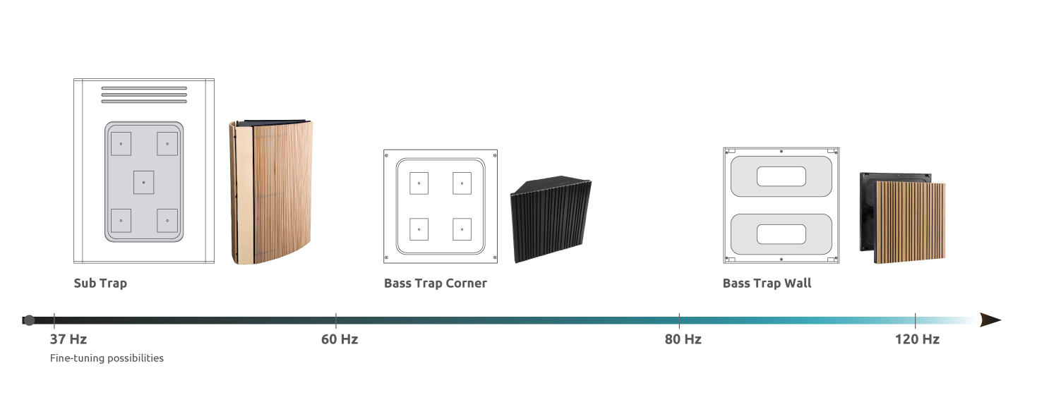
Mid-high frequency absorption is easily achieved through broadband porous absorbers and is readily available on the market—solutions for frequencies from 60 Hz to 120 Hz are considerably rarer and require distinct absorption techniques.
Treating even lower frequencies usually involve either vast custom-built solutions or structural alterations to the space.
The goal was to create a high-performance absorber with a tuneable resonant frequency that could effectively work down to 40 Hz. The tuneable element is essential, so a massproduced product could be adapted to target each rooms' characteristic resonant frequencie
A New Design Approach
To tackle these criteria, a novel approach to low- frequency absorber design was required.
Porous absorbers utilize a very large volume to reach a comparable performance and have an uneven absorption range—enough material to be effective at low frequencies will in turn have an exaggerated effect at high frequencies. Resonance absorbers (e.g., Helmholtz resonators) are more suited to actuate on acoustic pressure, although tuning Helmholtz resonators to be effective at low frequencies requires large depth perforations. The former requires massive volume, while the latter leads to a low ratio of effective exchange area over surface area, resulting in large areas of treatment to be effective.
These factors can make this technique impractical outside of large room treatment.
Diaphragm absorbers are a common tool utilized to attenuate standing waves as part of an acoustic treatment. They achieve a high- absorption coefficient, utilizing a relatively small volume. When paired with a porous acoustic core, they present a wider more linear absorption coefficient, making them a preferred option.
Diaphragm (or membrane) absorbers are a common tool utilized to attenuate standing waves as part of an acoustic treatment. They achieve a high absorption coefficient utilizing a relatively small volume. When paired with a porous acoustic core they present a wider, more linear absorption coefficient, making them a preferred option.
Diaphragm absorbers work on a simple principal: They are velocity transducers, transforming incident pressure into particle velocity that is then easily dissipated through porous absorption typically placed in the enclosed volume behind the membrane.
Traditional diaphragm absorbers employ a solid material, located over a sealed volume containing an absorptive acoustic core.
Incident pressure causes the membrane to move, generating work and movement—displacing air in the interior of the enclosed volume and conveying velocity to the air particles—that are then “forced” to interact with the porous acoustic core.
Porous materials react efficiently to air particle velocity—the air particles travel aconvoluted path through the inner matrix of the porous material, dissipating energy through isothermal losses.
Diaphragm absorbers also have their limitations— seeing as the performance range has a narrower bandwidth at lower frequencies—it is important to build the absorber to resonate at precisely the desired frequency. This is not easily accomplished.
Diaphragm absorbers are essentially mass-spring systems. The peak absorption range of a diaphragm absorber is determined by multiple factors. Mainly the stiffness and mass of the membrane, and also the stiffness of the air inside the enclosed volume.
While the resonant frequency of the cavity and core can be precisely determined the intrinsic properties of the membrane the Young modulus and the density— vary greatly in common membrane materials, which can be problematic for precise calibration.
In simple terms, the resonant frequency is determined by the following criteria:
Enclosed volume characteristics
- Overall dimensions and volume
- Quantity and absorption coefficient of acoustic core
- Stiffness of enclosed air—determined by volume and depth of the enclosed cavity
Membrane characteristics
- Area—As the area of the membrane increases, the weight also increases, contributing toward lowering the resonant frequency.
- Mass—Determined by the density of the component material and thickness— as the weight increases, the resonant frequency decreases.
- Stiffness—Determined by the Young modulus of the membrane.
As the stiffness decreases, the resonant frequency decreases.
The overall absorption coefficient is determined by the amount of energy lost to the porous acoustic core and through flexural losses in the membrane material. The larger the area and the lower the stiffness of the membrane, a higher quantity of air is displaced in the internal cavity, for a higher absorption coefficient.
This leads us to the main issue—larger membrane areas and lower stiffness decrease the resonant frequency, but this has a limit. To lower the resonant frequency, the membrane weight can be increased by using a thicker membrane or denser material, but these factors also influence the stiffness and make the device heavier and more difficult to activate.
Creating an Efficient high-performance Diaphragmatic Absorber
So, how do we create a high-performance diaphragmatic absorber that is efficient at low frequencies?
This question brough a new membrane design the weighted diaphragm.
It employs the same technique as a passive bass radiator—this membrane is composed by a mass suspended on an elastic membrane. This method guarantees range of movement (activation) and true pistonic movement, without forcing a compromise on mass (see Figure I).
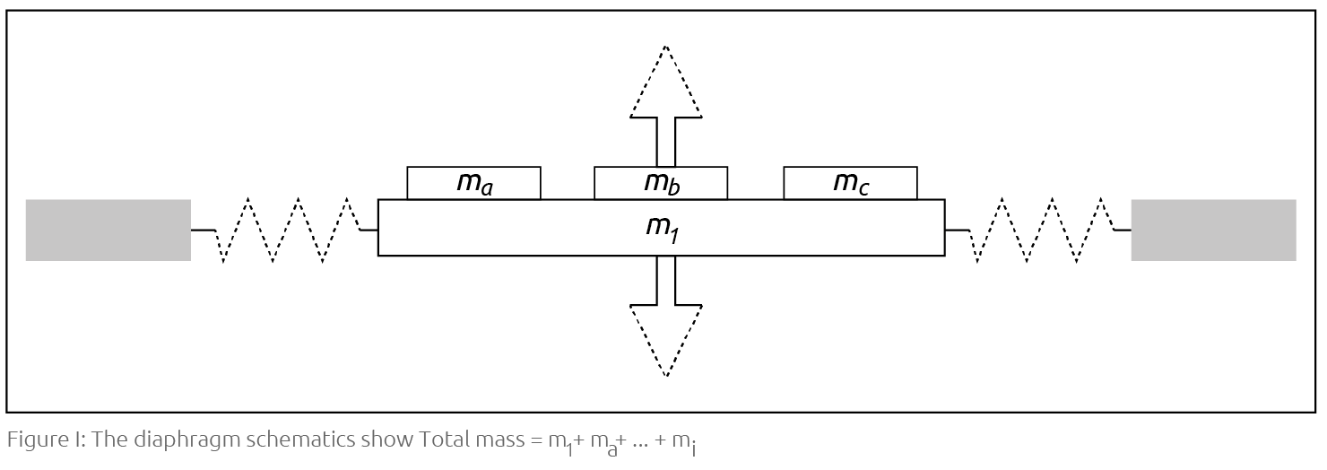
Separating the mass from the elastic component also allows for accurate prediction of theabsorber's performance, as the mass and the stiffness are separately controlled, making the system behave a s a predictable mass-spring system.
A further advantage is that the mass of the membrane can be easily modified, allowing to calibrate the resonant frequency of the system through altering the mass of the membrane without much effect on the stiffness. This results in a tuneable low- frequency absorber that presents a high absorption coefficient using a relatively small membrane.
Measurements
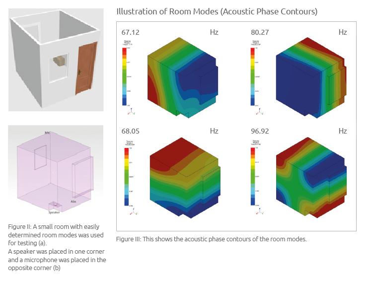
To validate the theory, empirical testing was carried out using a small room with easily determined room modes. The room was excited at the corner, and a microphone was placed in the opposite corner (see Figure II). The absorber panel was placed on the edge corresponding to maximum pressure of the axial and tangential mode at 68 Hz. The resonant frequency of the bass absorber itself was tuned to 62 Hz.
Room Conditions Used for Measurements
The room modes are shown at 67.12 Hz, 68.05 Hz, 80.27 Hz, and 96.92 Hz (see Figure III) and a small bass absorber “Corner Bass Trap” was used.
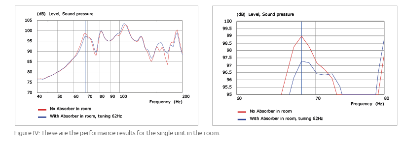
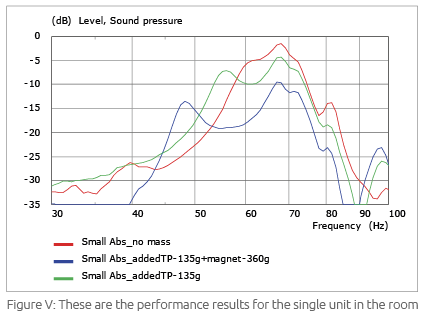
Figure IV shows the performance results for the single unit in the room.
Although the absorber is not perfectly tuned to the modal frequency of the room, it still offers significant absorption. A single 0.35 m2 unit offers an approximate 2 dB reduction at the resonant frequency of room— more units will obviously offer better performance.
Tuning the Membrane's Resonant Frequency
Measurements of mobility with the Laser Doppler Velocimeter (LDV) show the tuning of the absorber (see Figure V). The added masses are indicated in the legend. The original diaphragm (with no additional mass) is approximately 2 kg.
For this absorber, with only the diaphragm, the resonant frequency was 62 Hz. With 0.135 kg mass added to the diaphragm, the resonant frequency was 56 Hz. With 0.5 kg of mass added to the diaphragm, the resonant frequency was 48 Hz.
Mobility decreases as frequency decreases away from the original tuning frequency, possibly due to the panel becoming heavier and thus less mobile or because the excitation from the room mode is less effective—most likely it is a combination of these two factors. This concludes that there are limitations to the tuneable frequency range of the membrane, which is to be expected.
Diaphragm Movement
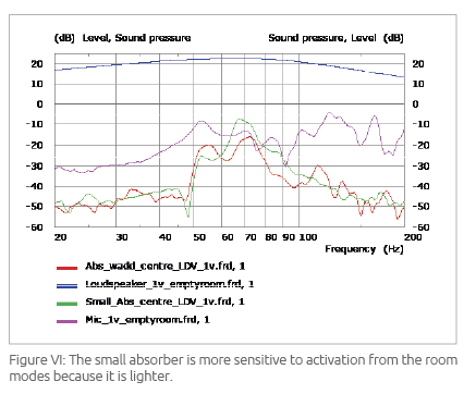
How much does the diaphragm move? Our laser measurements show the mobility or range of movement—of the diaphragm, compared to the speaker driving the room. They compare the diaphragm's activation when exposed to the sound field. The diaphragm's activation is obtained from the acoustic sound field, which means that the room's modal response is superimposed over the measured responses (i.e., it is the modal excitation of the room that makes the diaphragm move). Absorbers that move considerably with the pressure wave result in good absorbers, which means that accurate tuning of an absorber to modal frequency results in optimal absorption.
Activations at the level of the loudspeaker would result in very efficient levels of absorption. Absorber membranes move considerably less than loudspeaker and that's why they need to have much larger areas to be effective.
Figure VI shows that Mic1v_emptyroom is the acoustic room response. The small absorber is more sensitive to activation from the room modes because it is lighter.
Activation Level
Does higher sound pressure level affect absorber response?
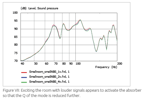
Figure VII shows the acoustic measurements. Exciting the room with louder signals appears to activate the absorber so that the Q of the mode is reduced further.
Note that we cannot totally discount the room effects as our measurement room is not perfectly rigid at low frequencies (i.e., the room becomes more absorbent as we drive it harder).
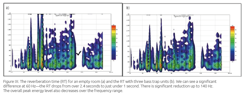
The three unites were tuned to one of the modal frequencies in the room—62 Hz. Figure IX displays the alteration in decay time of the low-frequency range in a spectrogram.
Performance for Three Units in a Medium-Sized Resonant Chamber
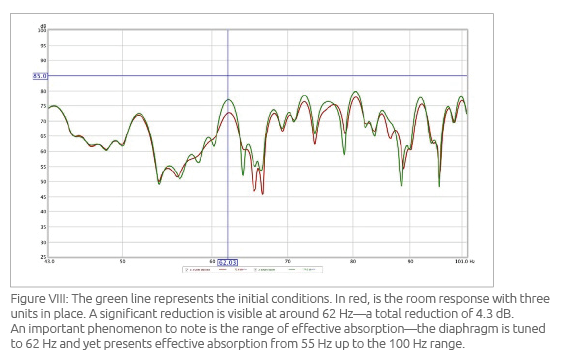
Further empirical testing was carried out using a medium-sized reverberation chamber (85 m3) and three “Corner Bass Trap” units (see Figure VIII). The same room setup was used, with the speaker placed in the opposite corner to the treatment, and the microphone placed in the opposite corner, in the resulting high- pressure zone.
Large Bass Absorber—"Sub Trap"
So far in this study all theoretical and empirical results have been shown for a small absorber unit—the “Corner Bass Trap.” All factors indicate that this style of diaphragm construction can be configured to be effective for even lower frequency. While the effective absorption range of the “Corner Bass Trap” is designed from 60 Hz to 80 Hz, we propose a configuration with effective absorption from 40 Hz to 60 Hz. This absorber— the “Sub Trap”—is divided into three independent closed volumes, in a prismatic configuration that exposes each diaphragm to the maximum pressure zones of each room mode. Further tests are being undertaken to completely characterize the behaviour of these larger scale diaphragms.
Understanding the Behaviour and Performance of Diaphragm Absorbers in a Room
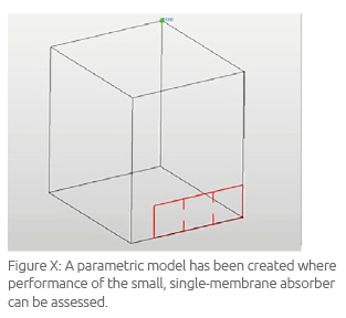
A parametric model has been created where performance of the small, single- membrane absorber can be assessed (see Figure X). All studies in this section use the small form factor working absorber that was identified in the measurements.
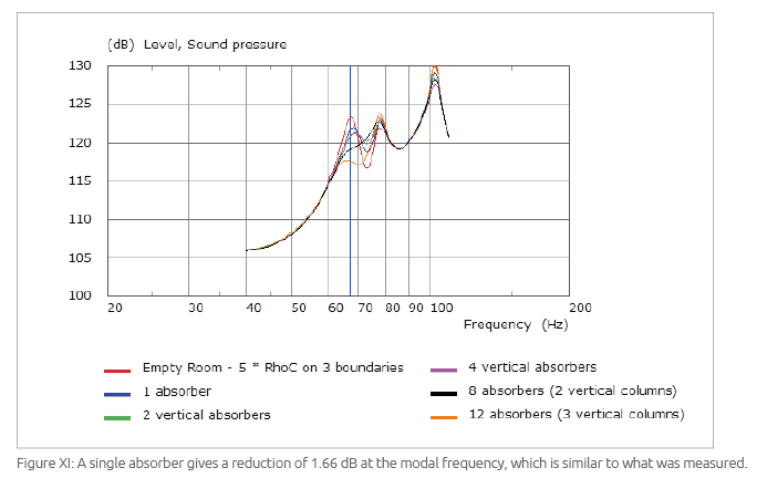
Results for simulations with a varying number of absorbers have been carried out. Impedances of room walls have been set at 5 × Rho × c to simulate the natural losses of the real room. The first problematic mode in this room is at around 68 Hz (see Figure XI). A single absorber gives a reduction of 1.66 dB at the modal frequency, which is similar to what was measured.
The location of the device is important. Stacking them up vertically (and entering a zone less involved in the mode shape to be absorbed) resulted in lower returns, which makes sense.
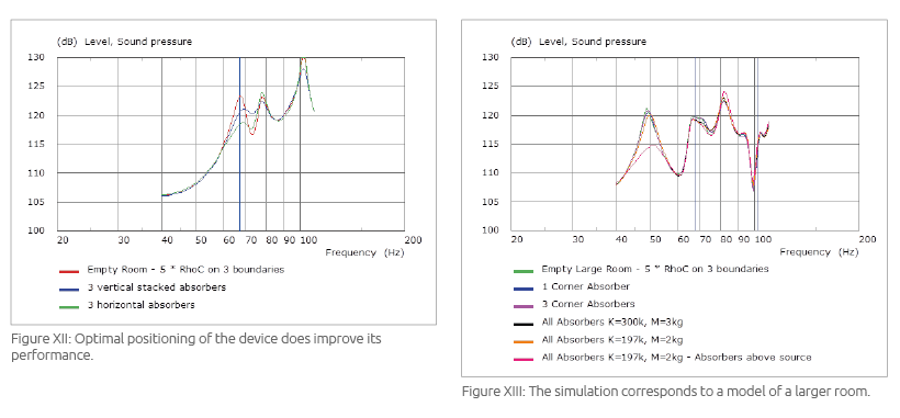
Placing them side by side along the wall gives better performance. To illustrate, Figure XII shows the results when we consider three absorbers, stacked vertically vs. side by side. As can be seen (and as we saw in practice during measurements), optimal positioning of the device does improve its performance. The green curves displayed in Figure XII shows that with only three absorbers lined horizontally on the floor of the room, a decent room treatment can be obtained.
Proof of this should be sought with measurements in a real room with various absorbers. Further simulations were carried out using the same setup, over a range of room sizes and number of units, with the objective to determine a correlation between location, quantity, and effect as shown in Figure XIII.
Quantifying Absorption Performance
Here we quantify the effectiveness of the small absorber in removing modal energy according to various simulation scenarios. Further simulations were run to ascertain the amount of absorption in terms of decibel drop at the modal frequency when:
- The same percentage of the room's surface area is occupied in three different sized rooms (the tuning of the absorbers was changed to follow the change in modal frequency at mode 1). This corresponds to creating simulations for three different rooms with increasing volume and covering an increasing amount of wall area with absorbers as the room size increases. However, to provide a relative comparison between the three rooms, the percentage area covered by the absorbers remains the same.
- The number of absorbers is increased in the same (small) room. In this study, a single room size is used but three difference simulations are run where the number of absorbers in the room increases.
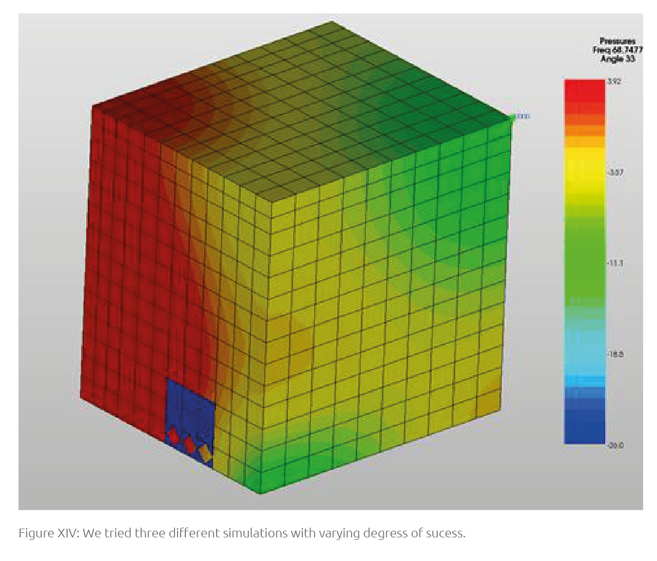
Absorbers are always placed at the maximum pressure zones of the modes they are designed to control (see Figure XIV). We have two examples of parametric rooms with absorbers. In Example 1, the three different room dimensions are shown in Table 1.
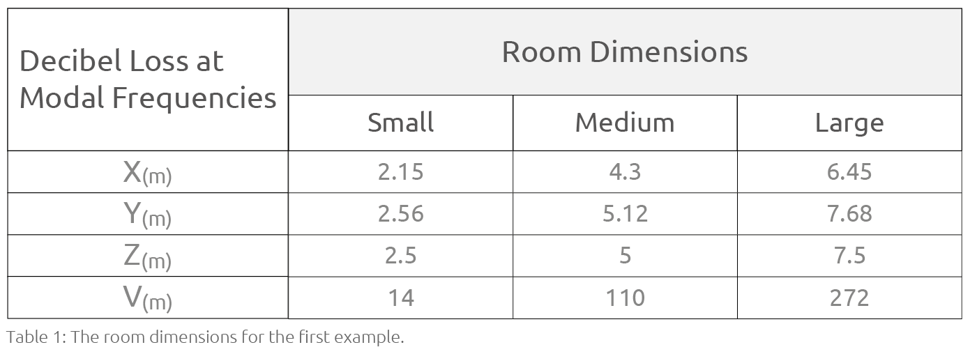
And the number of absorber units are one, four, and nine, respectively.
Figure XV shows the results.
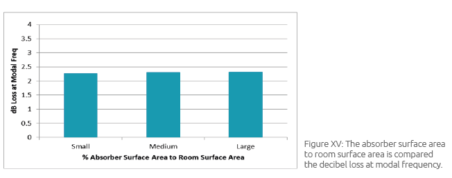
As expected, for the same proportion of absorption area, the same loss at the modal frequency is obtained. This shows that, as the room becomes larger (and the surface area increases) more absorption units are required to achieve the same degree of modal control.
In small volume rooms (less than 20 m3) a single unit is capable of providing demonstrable (but not sufficient!) absorption.
For large volume rooms (greater than 300 m3), a total of nine units are required to achieve around 2 dB reduction at the modal frequency.
In Example 2, the room size is kept constant, but the number of absorber units in the room is increased to assess the amount of modal reduction. The amount of absorption is provided as percentage of wall that has been covered by absorber units. The number of units required may then be determined from the room dimensions and absorber dimensions.
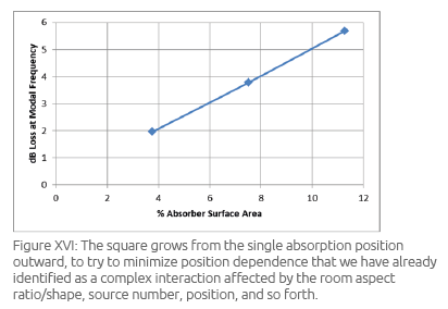
The simulations shown in Figure XVI correspond to a square of one, four, and nine elements. The square grows from the single absorption position outward, to try to minimize position dependence that we have already identified as a complex interaction affected by the room aspect ratio/ shape, source number and position, and so forth.
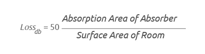
Using this expression, the number of required absorber units, at any of its tuning frequencies, may be prescribed for any room. A very simple model can be designed to calculate the amount of modal reduction (Loss) possible for a N number of absorbers in a Sw × Sd × Sh room:
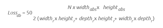
Note this expression holds for the size and tuning of the absorption measured and simulated. Other configurations might not present the same trend exactly.
Conclusion
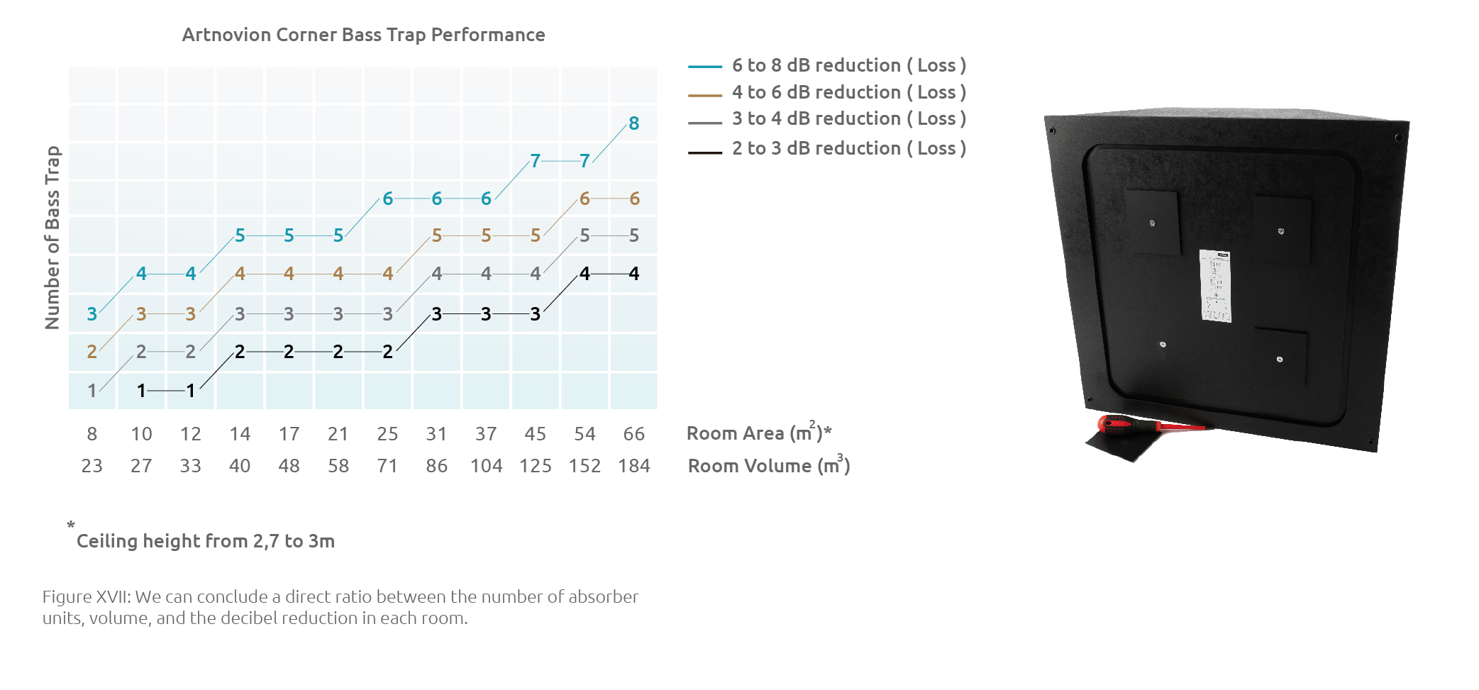
Standard representation of acoustic absorber products is based on the absorption coefficient, which is directly linked to reverberation time calculation. While reverberation time is a useful scale to estimate frequency response, especially in the mid-high frequency range, it gives no indication to the modal behaviour of a space. A more practical and simple approach is to present the attenuation value for a certain quantity of units in a certain sized room. A simple room measurement can then determine the required quantity of absorbers.
From the earlier examples, we can conclude a direct ratio between the number of absorber units, volume, and the decibel reduction in each room (see Figure XVII). To use the chart, simply cross reference the room size (in m2) with the desired decibel reduction to get the necessary quantity of Bass Trap panels.
As shown in both the simulationsand the measurements, the positioning of absorber units relative to the mode shapes extremely important.
All simulations have placed absorber units in the maximum modal pressure zones.
About the Authors
Dr. Bruno Fazenda and Kelvin Griffiths are researchers working together with Artnovion to develop innovative ways of facing acoustic problems. Fazenda has been working in acoustics since 2000 and is a specialist in room acoustics and psychoacoustics, in particular, the perception of modal problems in rooms. Griffiths is a specialist in numerical design and optimization, having vast experience in the design of loudspeakers and related products. Working directly for Artnovion on this project were Jorge Castro and Nathaniel Bailey. Castro is Artnovion's CEO and founder. He attended Salford University to complete a PG/Msc in Audio Acoustics. Nathaniel Bailey is Artnovion's R&D engineer and product development leader. All tests were developed at Electroacoustic Design, Ltd., in Porthcawl, South Wales.